2.2. Measuring the Driver
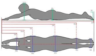
Buggy shell designs typically start with measurements of a driver or drivers. Ensuring the buggy can fit not only your current drivers but a wide range of potential future drivers is key for a team’s first buggy. Measurements should include all driving gear (helmet, mouth guard, athletic wear clothing). Use a flat board or table large enough for the driver to lay on, a round tube strong enough to hold ~100 lbs (mop/broom handle or cardboard shipping tubes work well) and a small tube that mimics a steering handle (Dry erase marker works well). The driver should lay down on their stomach on top of the board with their hands stretched out in front of them and head looking forward as if they are driving with the fake steering handle in their hands.
Once in this position, measure the distance from the steering handle in the driver’s hands to a few critical points: the elbows, shoulders, crown of the head, hips, knees, heels and end of toes, as shown in Figure 1. Follow this by measuring the width of the driver at their hands, shoulders, hips, calves and feet while maintaining the driving position. Finally, record the height from the floor to the crown of the driver’s head/helmet, hips/rump, calves, and heels.
A sample measurement guide is provided below, and a larger copy for usage can be found in Appendix X.
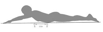
The final step is to remove the driver and place the board on top of the longer tube or broom handle, so the tube is perpendicular to the driver’s body. Lay the driver back down in the middle of the board in driving position. Have one person stand by the driver’s head and hold the front of the board, then roll the board forward and backwards until the board and driver are balanced on the tube. Measure the distance from the driver’s hands to the center of the tube to capture where their center of gravity is located, as in Figure 2.
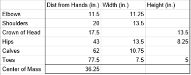
Place the measurements into an Excel table like the example below for easy reference during the next step. These measurements will be used throughout the instructions.
Advanced Design Tip: Cross Sectional Dimensions
To make the most aerodynamic and small shell designs, factor in the cross-sectional shape of the driver at the body points measured above (elbows, shoulders, hips, etc). A cross section in this case is the shape of the front fact of an object after it is sliced through at a certain point.
To accomplish this, have the driver lay on their stomach and grab two rulers. Lightly hold a ruler against the driver at the widest point of the elbows and record the height where the driver’s body and ruler first touch. Then measure the horizontal inset from the ruler to the driver’s body at each inch from the ground. The easiest way to accomplish this is laying the other ruler horizontally at each inch ticker and slowly sliding it towards the driver until it makes contact with their body. Record the measurement.
2.2.1. Alternative CG Measurement - Scale Method
Center of gravity (Cg) can also be measured using a board (like above), two scales (cheap bathroom scales are fine), and some simple force balancing (covered in most engineering intro courses). A thin bar/beam to rest between the board and scale to keep the weight centered is helpful, but not critical.
- Place the scales with their centers spaced such that one would be underneath the driver’s hands, and the other under the driver’s toes.
- Place the board evenly across the two scales
- If possible, lay a bar/beam across the center of each scale perpendicular to the length of the board. This will provide the most accurate measurement.
- With the board in place, zero the scales (tare), OR record the baseline weight reading so they can be subtracted for your final calculations.
- Carefully have the driver lay onto the board and check that her hands and toes are over the center of each scale. If not, repeat 1-4 until they are.
- Record the weight readings with the driver on the board subtracting the respective baseline readings as needed.
- Adding the scale measurements together should be roughly equivalent to the driver’s total weight
- Since we are looking for the distance from the hands to the CG, in a static system (i.e. nothing moving) all forces AND torques are equal, so treating the hands as a pivot point, we know that:
- Weight of Driver * Length to CG = Weight at Toes * Length to Toes
- Wdriver * Lcg = FToes * LToes
- Reorganizing that equation to solve for Lcg we get
- Lcg = WToes * LToes / Wdriver
- Typically, a person’s CG is somewhere around their navel or just below their waist.